
Gate valves are cut-off valves, usually installed on pipes with a diameter greater than 100mm, to cut off or connect the flow of medium in the pipe. Because the disc is a gate type, it is commonly called a gate valve. The gate valve has the advantages of low switching effort and low flow resistance. However, the sealing surface is easy to wear and leak, the opening stroke is large, and the maintenance is difficult. The gate valve cannot be used as a regulating valve and must be in the fully open or fully closed position. The working principle is: when the gate valve is closed, the valve stem moves downward depending on the sealing surface of the gate valve and the sealing surface of the valve seat to be highly smooth, flat and consistent. They fit each other to prevent the medium from flowing through, and rely on the top wedge to increase the sealing effect. The closing piece moves along the vertical direction of the center line. There are many types of gate valves, which can be divided into wedge type and parallel type according to their types. Each type is divided into single gate and double gate.
1.2 Structure:
The valve body of the gate valve adopts a self-sealing form. The connection between the bonnet and the valve body is to use the upward pressure of the medium in the valve to force the sealing packing to be compressed to achieve the purpose of sealing. The gate valve packing is sealed with high-pressure asbestos packing with copper wire.
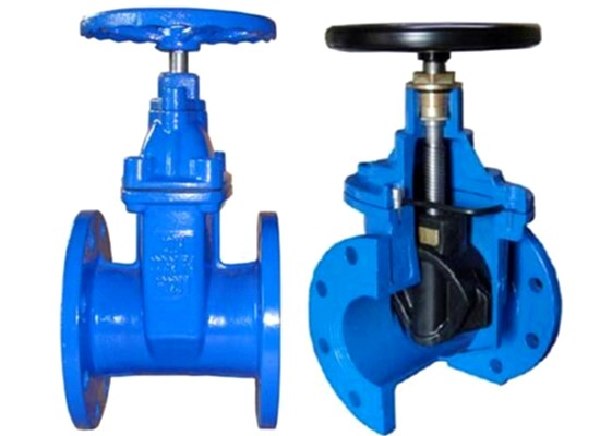
The structure of the gate valve is mainly composed of the valve body, the valve cover, the frame, the valve stem, the left and right valve discs, and the packing seal device.
2. Overhaul process of gate valve
2.1 Valve disassembly:
2.1.1 Remove the fixing bolts of the upper frame of the bonnet, unscrew the nuts of the four bolts on the bonnet, turn the stem nut counterclockwise to separate the valve frame from the valve body, and then use a lifting tool to lift the frame down , Put it in the right place. The stem nut is to be disassembled for inspection.
2.1.2 Take out the retaining ring at the sealing quadruple ring of the valve body, and press down the bonnet with a special tool to make a gap between the bonnet and the quadruple ring. Then take out the quad ring in sections. Finally, use a lifting tool to lift the valve cover together with the valve stem and the valve clack out of the valve body. Put it on the maintenance site, and pay attention to prevent damage to the valve clack joint surface.
2.1.3 Clean the inside of the valve body, check the joint surface of the valve seat, and determine the maintenance method. Cover the disassembled valve with a special cover plate or cover, and stick the seal.
2.1.4 Loosen the hinge bolts of the stuffing box on the valve cover. The packing gland is loosened and the valve stem is unscrewed.
2.1.5 Remove the upper and lower splints of the disc frame, take out the left and right discs, and keep the internal universal top and gasket. Measure the total thickness of the gasket and make a record.
2.2 Repair of various parts of the valve:
2.2.1 The joint surface of the gate valve seat should be ground with a special grinding tool (grinding gun, etc.). Grinding can use abrasive sand or emery cloth. The method is also from coarse to fine, and finally polished.
2.2.2 The joint surface of the valve clack can be grinded by hand or with a grinding machine. If the surface has a deep pit or groove, it can be sent to a lathe or grinder for micro processing, and it will be polished after all leveling.
2.2.3 Clean the bonnet and the sealing packing, remove the rust and dirt on the inner and outer walls of the packing press ring, so that the press ring can be smoothly inserted into the upper part of the bonnet, and it is convenient to compress the seal packing.
2.2.4 Clean the inner packing of the valve stem stuffing box, check whether the inner packing seat ring is intact, the gap between the inner hole and the cutting rod should meet the requirements, and the outer ring and the inner wall of the stuffing box should not be jammed.
2.2.5 Clean the rust on the packing gland and pressure plate, and the surface should be clean and intact. The gap between the inner hole of the gland and the cutting rod should meet the requirements, and the outer wall and the stuffing box should be free from jams, otherwise repairs should be carried out.
2.2.6 Loosen the hinge bolts, check that the threaded part is intact and the nut is intact, can be lightly screwed to the root of the bolt by hand, and the pin should be flexible to rotate.
2.2.7 Clean up the rust on the surface of the valve stem, check for bends, and straighten if necessary. The trapezoidal thread part should be intact, without breakage and damage, and be coated with lead powder after cleaning.
2.2.8 Clean the quad ring, and the surface should be smooth. The plane must not have burrs or curling edges.
2.2.9 All fastening bolts should be cleaned, the nuts should be complete and flexible, and the threaded parts should be coated with lead powder.
2.2.10 Clean the stem nut and internal bearing:
①Remove the valve stem nut lock nut and the fixing screw of the housing, and unscrew the lock screw in a counterclockwise direction.
② Take out the stem nut and bearing, disc spring, and clean it with kerosene. Check whether the bearing rotates flexibly and whether the disc spring has cracks.
③ Clean the valve stem nut, check whether the inner bushing trapezoidal screw is intact, and the fixing screw with the shell should be firm and reliable. The wear of the bushing should meet the requirements, otherwise it should be replaced.
④ Coat the bearing with butter and put it into the stem nut. Disc springs are combined as required and reassembled in sequence. Finally, lock it with a lock nut, and then fix it firmly with a screw.
2.3 Assembly of gate valve:
2.3.1 Mount the qualified left and right discs on the stem clamp ring and fix them with the upper and lower clamps. The inside of it should be put into the universal top, and the adjustment gasket should be tested according to the maintenance condition.
2.3.2 Insert the valve stem together with the valve disc into the valve seat for test inspection. After the valve disc and the sealing surface of the valve seat are in full contact, it should be ensured that the sealing surface of the valve disc is higher than the sealing surface of the valve seat and meets the quality requirements. Otherwise, it should be adjusted. The thickness of the gasket at the top until it is suitable, and the anti-return gasket is used to seal it to prevent it from falling off.
2.3.3 Clean the valve body, and wipe the valve seat and disc. Then put the valve stem and the valve disc into the valve seat, and install the valve cover.
2.3.4 Install sealing packing as required on the self-sealing part of the bonnet. The packing specification and number of turns should meet the quality standard. The upper part of the packing is pressed tightly with a pressure ring, and finally closed with a cover plate.
2.3.5 Assemble the quadruple ring in sections one by one, use a retaining ring to expand it to prevent it from falling off, and tighten the nut of the bonnet lifting bolt.
2.3.6 Fill the valve stem sealing stuffing box with the packing as required, insert it into the performance gland and pressure plate, and check it tightly with a hinge screw.
2.3.7 Install the bonnet frame, rotate the upper stem nut to make the frame fall on the valve body, and fasten it with connecting bolts to prevent it from falling off.
2.3.8 Install the valve electric drive device; the top wire of the connection part should be tightened to prevent it from falling off, and manually test whether the flap switch is flexible.
2.3.9 The valve nameplate is clear, intact and correct. The maintenance records are complete and clear; and the experience has been accepted as qualified.
2.3.10 The pipelines and valves have complete insulation, and the maintenance site should be cleaned.
3. Quality standards for gate valve maintenance
3.1 Valve body:
3.1.1 The valve body should be free of defects such as blisters, cracks and scouring, and should be dealt with in time after discovery.
3.1.2 There should be no debris in the valve body and pipeline, and the inlet and outlet should be unblocked.
3.1.3 The screw plug at the bottom of the valve body should ensure reliable sealing and no leakage.
3.2 Valve stem:
3.2.1 The curvature of the valve stem should not be greater than 1/1000 of the full length, otherwise it should be straightened or replaced.
3.2.2 The trapezoidal thread part of the valve stem should be intact, free from breakage, snapping and other defects, and the amount of wear should not be greater than 1/3 of the thickness of the trapezoidal thread.
3.2.3 The surface is smooth and clean, free of rust and scale, and the sealing contact part with the packing must not have flaky corrosion and surface delamination. The uniform corrosion point depth ≥ 0.25 mm should be replaced with a new one. The finish should be guaranteed to be above ▽6.
3.2.4 The connecting thread should be intact and the pins should be fixed reliably.
3.2.5 After the stub and stub nut are combined, they should rotate flexibly, without jamming during the full stroke, and the threads should be coated with lead powder for protection.
3.3 Packing seal:
3.3.1 The pressure and temperature of the packing used should meet the requirements of the valve medium, and the product should be accompanied by a certificate or necessary test appraisal.
3.3.2 Packing specifications should meet the size requirements of the sealed box, and should not be replaced by packing that is too large or too small. The height of the packing should meet the valve size requirements, and a thermal tight margin should be reserved.
3.3.3 The filler interface should be cut into an oblique shape, the angle is 45°, the joints of each circle should be staggered by 90°-180°, the length of the filler after cutting should be appropriate, and there should be no gap or overlap at the interface in the stuffing box Phenomenon.
3.3.4 The packing seat ring and packing gland should be intact and free of rust and dirt. The stuffing box should be clean and smooth. The gap between the gate rod and the seat ring should be 0.1-0.3 mm, and the maximum should not exceed 0.5 mm. The packing gland and seat ring The gap between the periphery and the inner wall of the stuffing box is 0.2-0.3 mm, and the maximum is no more than 0.5 mm.
3.3.5 After the hinge bolts are tightened, the pressure plate should remain flat and evenly tightened. The inner hole of the packing gland and the pressure plate should be consistent with the clearance around the valve stem. The packing gland should be pressed into the packing chamber to be 1/3 of its height.
3.4 Sealing surface:
3.4.1 The sealing surface of the valve disc and valve seat after maintenance should be free of spots and grooves, and the contact part should occupy more than 2/3 of the valve disc opening width, and the surface finish should reach ▽10 or more.
3.4.2 Assemble the test valve disc. After the disc is inserted into the valve seat, the valve core should be 5-7 mm higher than the valve seat to ensure tightness.
3.4.3 When assembling the left and right discs, ensure that the self-adjustment is flexible, and the anti-falling device should be intact and reliable.
3.5.1 The inner bushing thread should be intact, and there should be no broken buckles or random buckles, and the fixing with the outer shell should be reliable and no looseness.
3.5.2 All bearing parts should be intact and flexible to rotate. There are no flaws, such as cracks, rust, heavy leather, etc. on the surface of the inner jacket and the steel ball.
3.5.3 The disc spring should be free of cracks and deformation, otherwise it should be replaced with a new one. 3.5.4 The fixing screws on the surface of the lock nut shall not be loosened. The stem nut rotates flexibly, and the axial clearance is guaranteed but not more than 0.35 mm.
Post time: Sep-10-2021